Two Untersatzen A On One Stand

Untersatzen A and B Together On One Stand
A Großer Feldklappenschrank with an Untersatz A was purely an OB (Ortsbatterie Bretieb) switchboard, in that all field telephones connected to it had battery-powered handsets and magneto powered ringers. Unlike the Untersatz C, none of the telephones had to be equipped with an SB Zusatz 33.
The upper front panel of the Untersatz A had 10 jack sockets and 10 signal flaps. The sockets were used by the operator to monitor telephone connection with the white plug. The flaps indicated when a connected call was ended. At the end of a call, one of the parties would crank the magneto on their telephone. This would cause the flap to drop associated with the black and red plug used to connect the call. There was also a single sternshauzeichen on the upper front panel that was used to indicate presence of outgoing ringer electrical current.
Towards the rear of the desktop panel was 10 red plugs and 10 black plugs. The plugs were paired in 10 pairs. The red plugs were used to answer calls. The black plugs were used to connect the calls. The white plug was used by the operator to monitor connected calls.
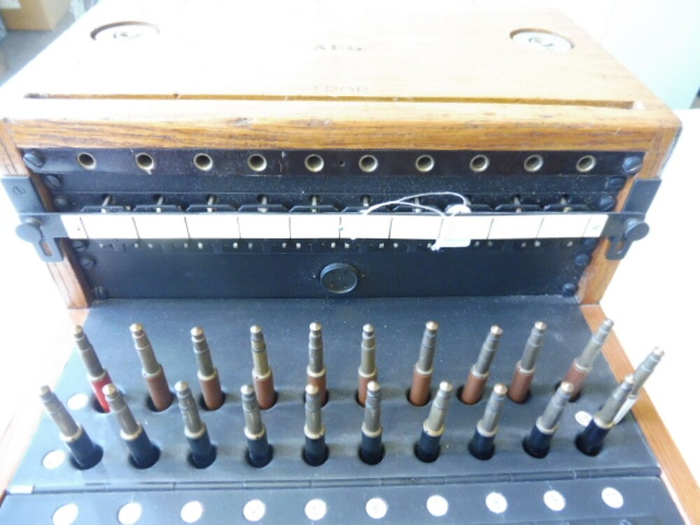
Untersatz A Upper Front Panel and Rear Desktop
In the middle of the desktop were 10 Kellogg switches with red handles. Each Kellogg switch was associated with a red and black plug. In the center, or rest position, the Kellogg switch is disconnected. Pulling the switch forward places it into the answer or “Abfrag” position. In the answer position, the operator can answer an incoming call once the associated red plug in inserted in the caller’s jack socket.
After the caller tells the operator which party he wishes to be connected to, the operator places the associated black plug in the party’s jack socket. The operator then pushes the associated Kellogg switch backwards to place it into the call or “Rufen” position to ring the party’s field telephone. Ringing current is either generated by a Polwechsler or crank magneto.
In the answer position, the Kellogg switch stays in place. The switch must be returned to the center position (middle) by hand. From the call position, a spring automatically returns the switch to the center position.
In the case were there is a delay in connecting with the called party, the operator can use the 10 white buttons located between the row of Kellogg switches and the row of black plugs. Each button is used for calling back the caller connected via the associated red plug. Pressing the white button connects the caller’s telephone to either the Polwechsler or crank magneto.
The button in the center-left of the desktop is the monitoring button. The operator could use the button and the white plug to monitor the conversations of the connected participants without disturbing the participants. When the button is pressed, the microphone of the switchboard handset is muted.

Untersatz A Desktop
On the left of the lower front panel of the Untersatz A, are two sockets that could be used to plug in a handset or a headset/chest microphone. In the center are two switches… One with a red handle and one with a white handle.
The switch with the red handle is only used if the switchboard is one of at least two in an exchange. If the operator is going to leave the Untersatz A, he or she can throw the red switch to transfer control of the Untersatz A to the switchboard to the left.
The switch with the white handle allows the operator to automatically generate ringing current via a Polwechsler or manually generate ringing current via a crank magneto. The magneto crank fits in the hole on the right of the lower front panel.

Untersatz A Lower Front Panel
The Untersatz A panel lifts to reveal the wiring, main power board, and the crank magneto. A hole is situated at the center of the main power board to facilitate wiring access through the bottom of the Untersatz A.
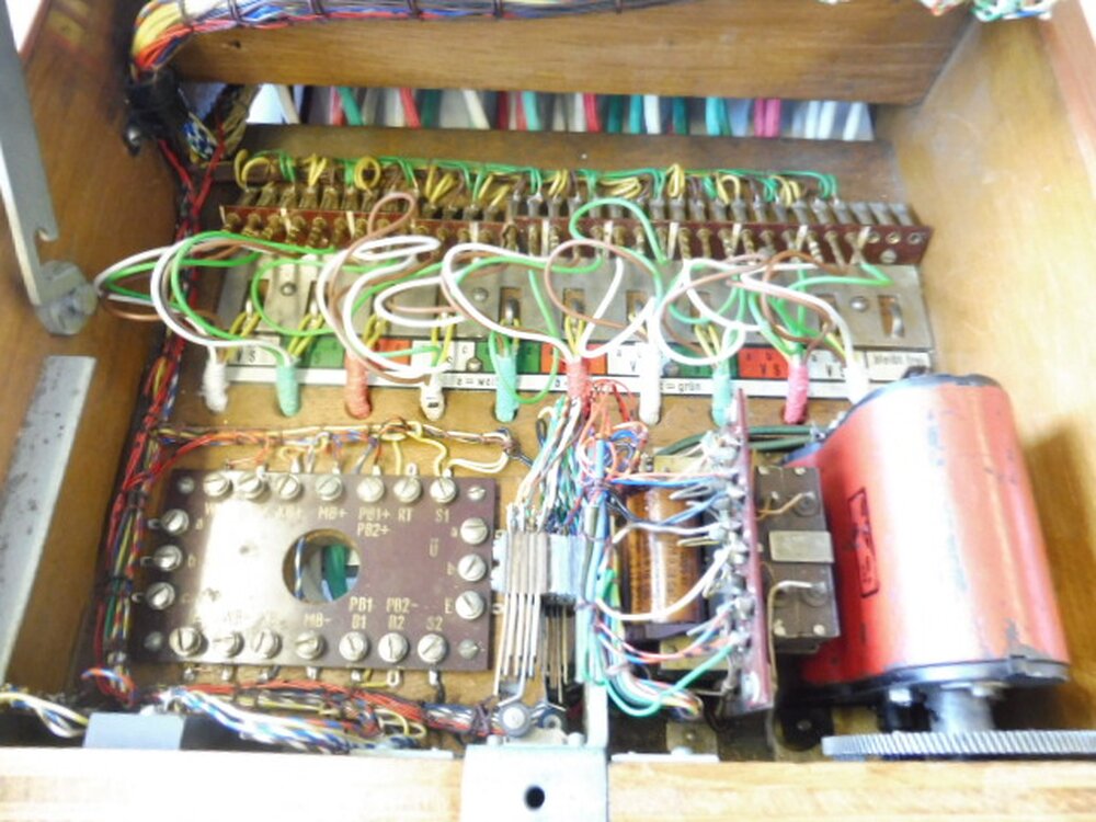
Inside the Untersatz A
At a minimum, the Untersatz A requires a 1.5 Volt battery (MB) for microphone power in the handset or the chest microphone. The MB battery was most likely a large T1 battery.
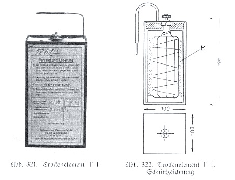
1.5 Volt T1 Battery
The Großer Feldklappenschrank Untersatzen and modules could be interconnected at the rear by 30 conductor cables and 30 pin plugs to form large exchanges serving hundreds of telephone lines.
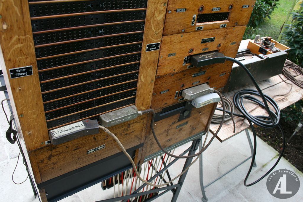
Rear View of an Untersatzen A and B Combo
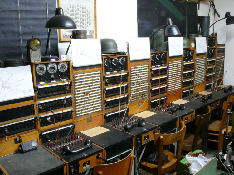
Large Switchboard Exchange
Don’t forget to check out my friend Albert Lampl’s website to learn more about the Großer Feldklappenschrank: https://der-fernmelder.de/
Check out my new book on WW2 German field telephone equipment… https://www.lulu.com/en/us/shop/rotwang ... ageSize=4