Lightning arrestor (Feldblitzableiter) panels are used to protect telecommunications equipment from high voltages and strong electrical currents. These can be caused during thunderstorms or by adjacent power lines through direct contact or induction. These high voltages and strong currents can penetrate into the telecommunications system and cause damage.
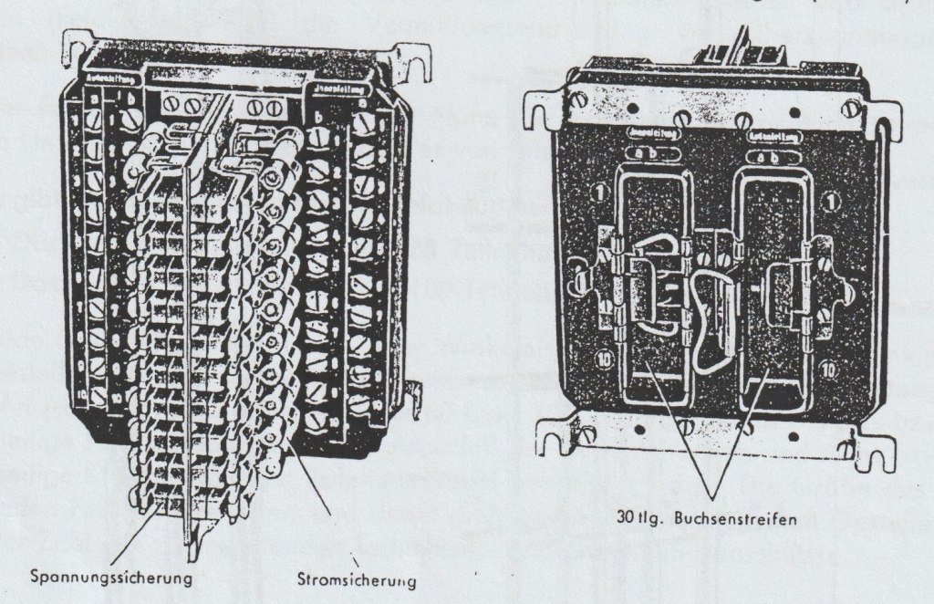
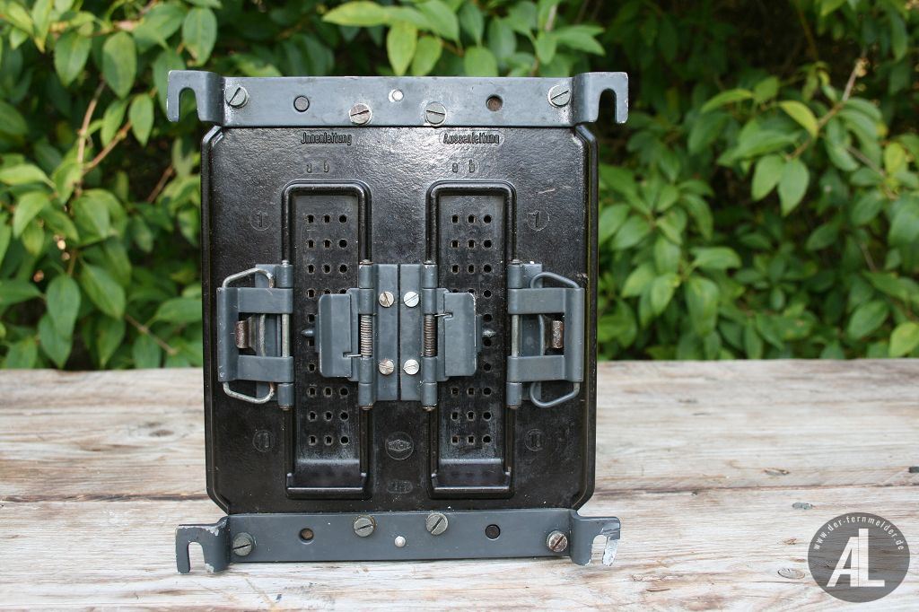
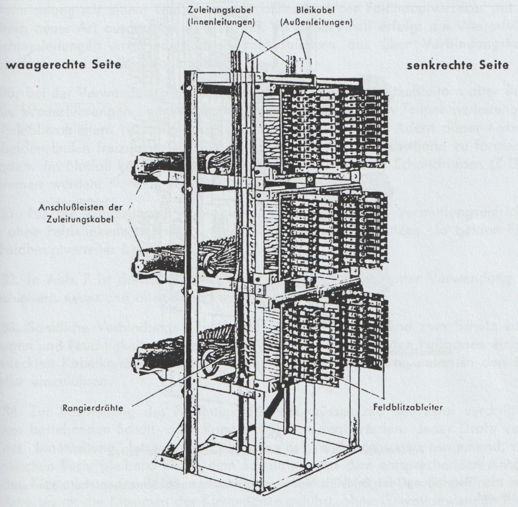
Each ten-line field lightning arrestor panel is equipped with 20 current fuses (Stromsicherung) and voltage electrodes (Spannungssicherungen). These are mounted on a base plate. The base plate made of insulating material and contains line terminals marked "a" and "b" along two sides. Ten pairs of terminals along one side are for “outer lines” (Außenleitung). Ten pairs of terminals along the other side are for “inner lines” (Innenleitung). On the rear of the plate are two 30-pin sockets for the “outer lines” (Außenleitung) and “inner lines” (Innenleitung). The terminals and the sockets are connected by insulated wires connected to the associated lightning arrestors and fuse holders. Normally, the outer lines go to out to the field and the inner lines go to the switchboard.
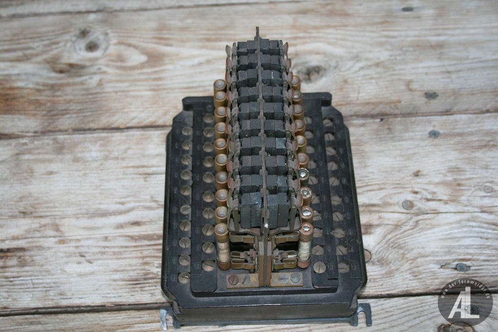
My friend Albert Lampl has photos of lightning arrestor panels from his collection. You can view more photos at: https://der-fernmelder.de/zubehoer-nach ... chutzsatz/
Here's how the panels work: Each of the 20 telephone lines ("a" and "b") has a pair of rectangular carbon voltage electrodes. Each pair of electrodes is separated by a thin layer of mica or cellite (about 0.12 to 0.15 mm thick) to normally insulate the electrode pairs from each other. The mica or cellite is perforated. Each electrode sandwich is situated between electrical contacts for each “a” and “b” telephone line and electrical ground (Erde) contacts. The carbon electrodes make electrical contact with the contacts and are held in place by spring pressure. During normal operations the telephone line contacts are insulated from electrical ground contacts.
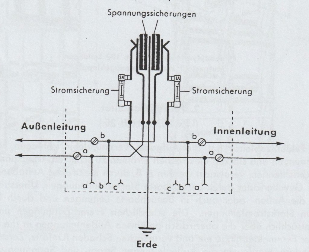
High electrical voltages have the property of arcing across short air gaps. Short air gaps are created by the perforations in the mica or cellulite layer between the electrodes. These air gaps are just dimensioned so that they are only penetrated by abnormally high voltages, such as that created during a lightning strike. However, the normal operating voltages of telecommunications equipment cannot penetrate these air gaps.
The current fuses are rated at 3 amps. They consist of a glass tube which has a metal cap at both ends. Each cap has a blade which is inserted into the fuse holder. Inside the tube is a thin wire that is connected to the two blades and melts at a current greater than 3 amps. Each of the 20 “a” and “b” lines has a fuse.
In large switchboard exchange installations having dozens of incoming field telephone lines, each arrestor panel is designed to fit in a metal rack in the building.
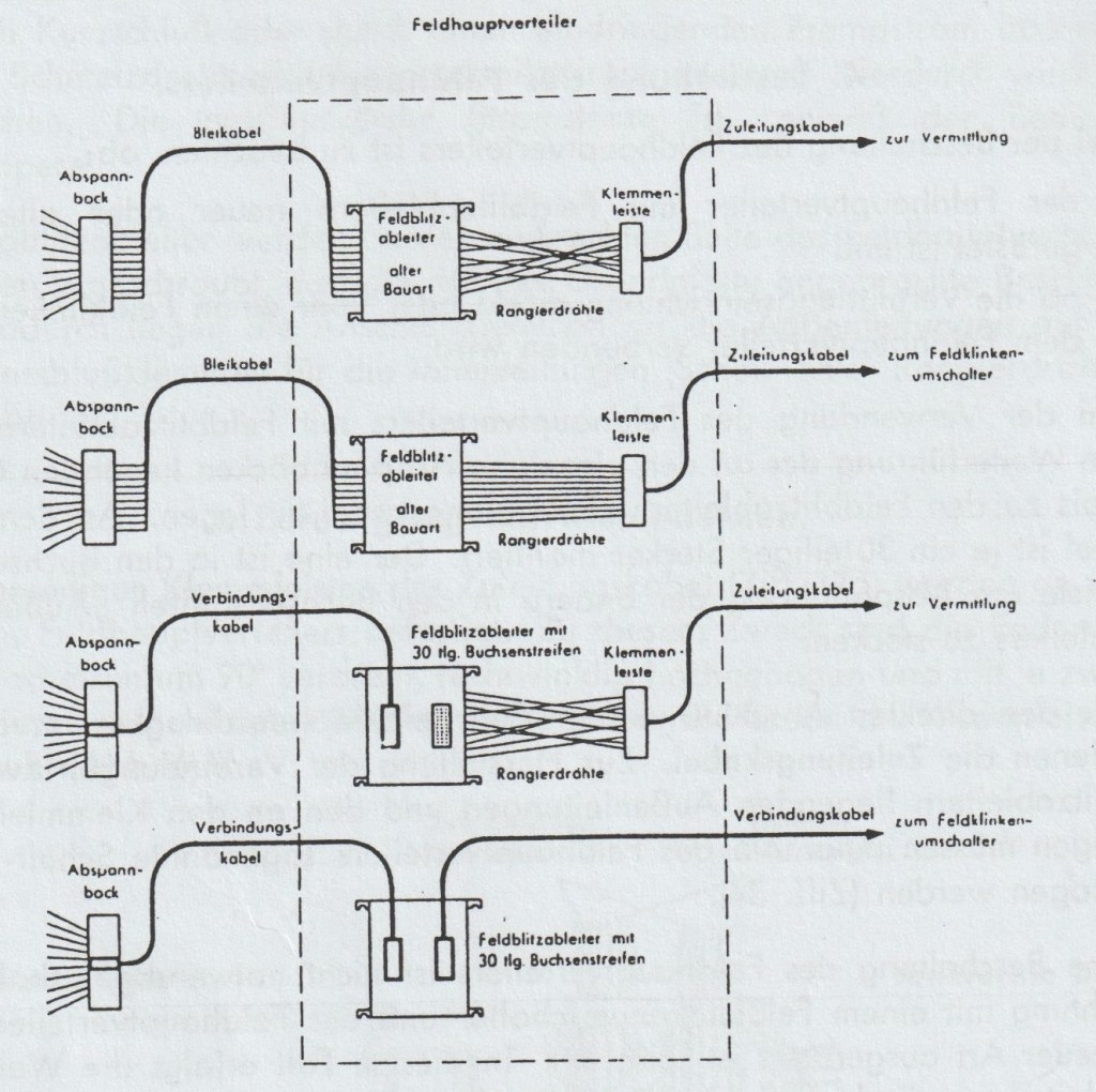
The following figure shows how the panels can be connected to field telephone lines using either the individual "a" and "b" terminals or cables.
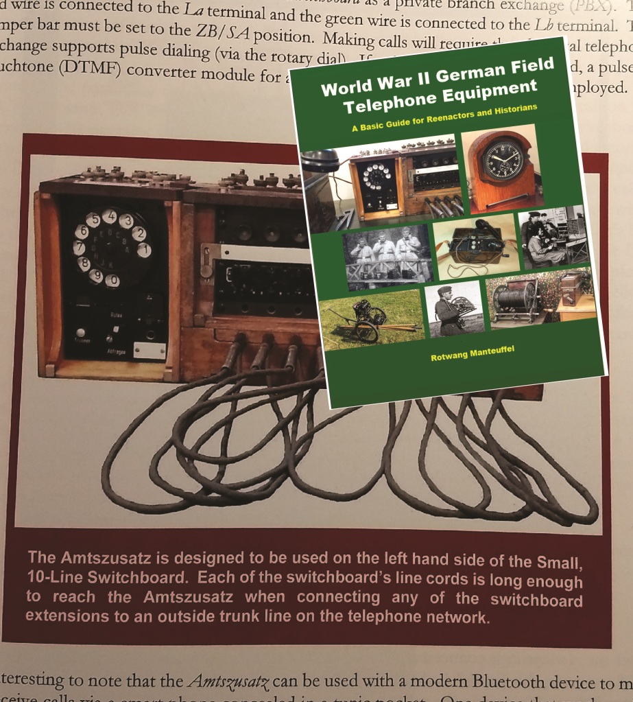
Check out my new book on WW2 German field telephone equipment… https://www.lulu.com/en/us/shop/rotwang ... pageSize=4