So this topic should be filled up with all existing knowledge on this high sophisticated technical equipment necessary for naval purpose, but installed on land. This item has been treated several times in general or for specific details in very different threads, difficult to find and to identify now.
All existing (and published) drawings of the combined two "Regelbauten S473 / S483", built twice at "Stützpunkt Karola Ro 429, Ile de Ré", and published just after the war (Pinczon) till today show the Bunker in principle in the right way. But all drawings are more or less wrong in regard to proportions and dimensions. The best I know are those from "Ph.Truttmann", and "P.Rhode" (published by "Interfest", basis 1979). Often other plans are just improved or even worse copies of existing ones. Original "Pläne" are not known (?).
I am very interested in the fortifications of Ile de Ré due to the fact that we have been there since 1981 - minimum once, sometimes twice a year from 3 days up to 4 weeks, only 3 km away from Kora-Karola as the most interesting Stp. (for me).
This means that I have had the opportunity to have a look at "Käthe, Kora, Karola & Co." more than 50 times from 15 minutes up to several hours, sometimes together with my friend Jean-Luc (Jazote).
During the last years I have been concentrating especially on the exploration of (different) specific items. E.g. first to find all the over 150 buildings, and remains (very difficult and time consuming without the multiple at present day existing footpath) or the question about the installation of the 6x Flak 75mm Vickers, or the fascinating (for me) prefabricated barracks which I call "Lego-houses"
I am normally not interested in Bunker dimensions.
As the question raised last year if the original twin 20,3cm naval turret had been integrated into the two combined Regelbauten WITHOUT any modifications even for the peripheral equipment, I decided to find out the exact dimensions of the Bunker as built (sorted from the formwork) in order to clarify this question. A 3D-plan using an CAD-program from my architect-children had to be drawn. All hundreds of dimensions in this plan should have an accuracy each of +- 2cm and perfectly fit together to a whole entity. Instead this 3D plan of the turret "Dora" and its Bunker will become a “sketchup model”, with the help of a 3D specialist and friend of mine. I didn´t imagine what complex and laborious task that would be – all z-components (heights) were missing or wrong. Even Dirk with his experience could not avoid some mistakes (at least one major) in measuring the “only” x-y coordinates. By the way I made more than one mistake, one reason for the multiple visits.
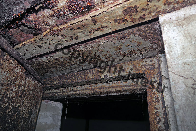
Just a little example of a “simple” door lintel:
When mesured the height of the outer steel beams on both sides I didn´t realize the two-step shape inside the lintel – and by designing later nothing would fit for unknown reason.
Another one are the 9 (!) different room heights only for the basement…………
juestr 2018
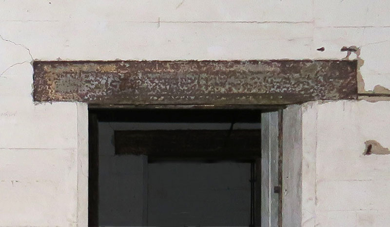
On the other opposite side of the wall this door lintel looks quite simple (to design)
Between September 2017 and June 2018 I visited the site ten times, 3 visits to "Anton" and 7 to "Dora" - and being now at home I should return soon to look again for some missing details.
Very shortly I will give you some major results of my studies with the hope of multiple answers and knowledge input:
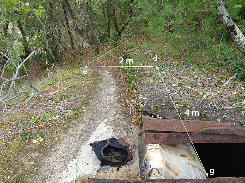
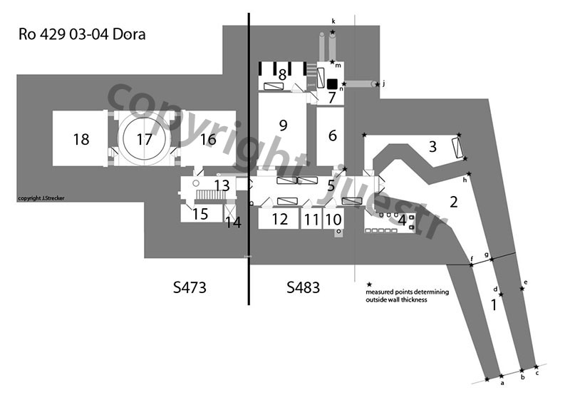
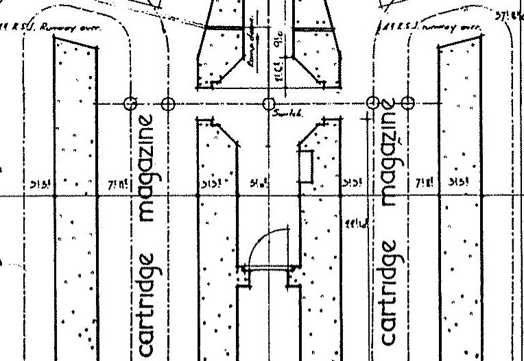
1. Being an artillery Bunker > 20 cm both Regelbauten have been built in protection A as stated in the rules. This means in contrast to nearly all drawings - especially the very first one from Pinczon - that all outer walls and the roof are made of 350 cm concrete. This can easily been prooved. The right wall seems to be conical from 150 cm at the exit to about 350 cm at the opposite side. The outside top of the walls seems to be skewed.
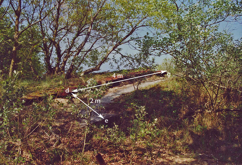
The following 2 images show the mesuring points as indicated in the following plan below.
juestr 2018
juestr 2017
2. The first turret became operational on January, 30, 1944. I think that the two Bunkers were built one after the other by overlapping time. There are some important differences between Anton (Ro429 01-02) and Dora (Ro429 03-03) and quite a lot in details. Dora seems to me a more simplified and improved version of Anton, using less concrete in combining these two Regelbauten. So I suppose Dora was built second.
3. The naval turret was integrated into the building without any geometric modification. This includes the conveying systems for the shells from store-rooms to the shell-platform of the turret.
4. In the building(s) there are no armoured doors, but only Gasschutztüren type 19P7 or similar navy versions and wooden doors. One exception might be the two-wings transition door between S483 and S473 (120w x180h cm) which has disappeared. Might be the same naval T-model which can always be seen in the "Leitstand" S497.
5. We can see the remains of 7 triple bunks(= 21), navy version made in Berlin, placed wherever space was available even just beside or under machinery. Despite a "comfortable" lavatory, the Bunker seems not to have been made for permanent housing of the gunners.
Now let´s have a look at the different locations shown on my floor plan of Ro429 03-04, Dora.
a lot of images can be found here (page 6..):
viewtopic.php?f=70&t=205550&hilit=ro+42 ... 0#p1854127
viewtopic.php?f=70&t=192274&hilit=ile+de+re+kora+karola
Regelbau S483
rooms 1+2:
the entrance of S483, and the only one for both buildings. This entrance has been extended by two side walls, open above, originally only covered by a "camouflage net". The two embrasures are (of )type 483P2. The overall length from the entrance to the right embrasure is 20 m.
room3:
entrance defense room with inner side of embrasures. 3 bunks which were to be folded before using the machine-gun.
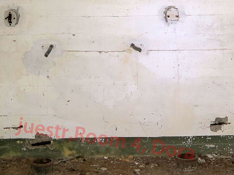
room 4:
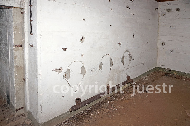
lavatory with 5 basins, 3 urinals (type "la Rochelle", seen in a book of A.Chazette) and two toilets. The urinals fit exactly to the traces at the wall. No showers exist in this room as told sometimes.
juestr 2017
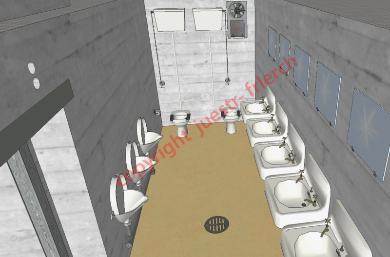
3D drawing is still under construction
room 5:
main vestibule/corridor of S483 with different locations on the left and right side. On the right were located all the engine related rooms.
room 6:
location for fuel tanks
room 7:
this room seems to have sheltered water cooling units for the Diesel engines by use of fresh air (Einheitskühler). Amongst the machinery 3 bunks were fixed to the wall. These bunks disappeared only a few years ago.
In the outer walls are one (tube) opening of 50 cm and two others of 65 cm. All of them used to lead outside to the roof. The middle one, in front of the support frame and the concrete pedestal was also leading downwards and into an unknown kind of room / space going to the left and right side at the bottom. Possibly this "free space" is already outside of the building, in either case near the outside of the wall (3,50m). Unfortunately, the video taken in June has completely failed. I am not really familiar with the function of these cooling devices. In either case it seems to be more “complicated” (why a third big air in- or output duct?) than the simple cooling circuit with “Einheitskühler” found in the Leitstand S497.
Maybe we can get some informations from Janef of the corresponding modalities in Austratt. Or by Jos who showed only parts of an “Rückkühler” circuit.
viewtopic.php?f=70&t=227917&hilit=R%C3% ... r#p2073397
Looking at the whole piping it might be more understandable.
See also: viewtopic.php?f=70&t=192274&p=2072076&h ... a#p2072059
Here Jos tells us about an outside 1700 (??) water tank seen on the legenda of S483 just beside the main bunker. At “Lindemann” we can see this “side watertank room”. But in case of “Anton” and “Dora” no traces are to be seen, neither on historical pictures. On the other hand we have a big cistern and a well between both turrets (Jazote told about that) and no barracks etc. in the near vicinity. Why not water reserve for cooling purpose of the engines here !?
IGN 1963 (extract)

room 8:
water tanks (scrapped) for the cooling of the engines, and the 3 bunks.
Compared to “Gr. Kurfürst” the volume of these tanks alone does not seem sufficient to me.
room 9:
engine room with one main (100 kW) and one auxiliary (50 kW) diesel engines (like half Austratt/Oerlandet ??) and its generators. Electrical equipment on the left wall.
Does anybody have a more detailed technical piece of information?
From the upper left corner, a bigger cable duct is leading along the wall of room 13 to the bottom of room 19 through the floor. Probably from here and/or the deep manhole in the floor of room 19, just beside the duct, a channel below the shell store (room 22) is leading to the bottom center of the rotating turret. There is NO cable channel (to be seen) below the buildings S483/473 from the engine room to the turret as shown by Pinczon and others.
Unknown door type (160cm width), disappeared or was never installed.
room 10:
“Fresh” water supply room with well pit (depth now 5m) and pump. Wooden door.
room 11:
Unknown purpose. No traces of beds or electrical equipment. Just switch and light. May be officer / chief chamber. Wooden door.
room 12:
Workshop and storage room for technical spare parts. Wooden door
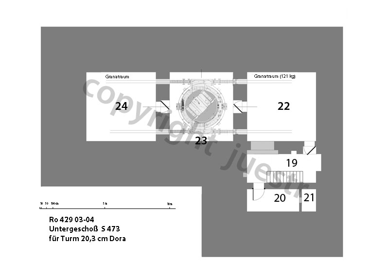
Regelbau S473
room 13:
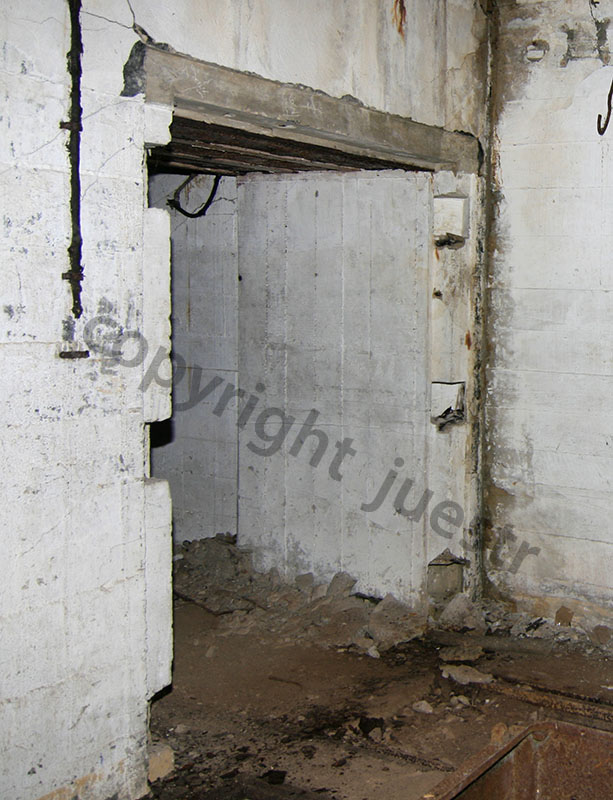
Main corridor. Entrance through probably armoured double-wing door 1,20 x 1,80 m, naval T-type. This door has been scrapped. On the right side is the entrance through "Gasschutztür" to cartridge store room 16 and further to turret pit 17. On the left side staircase to the basement and opening in the wall to room 14.
after studying the “Panzertür” thread (viewtopic.php?f=70&t=69948&hilit=panzert%C3%BCr)
I am nearly convinced that the entrance door was planned as a T10 type door. I am no an expert and unfortunately all the shared info links do not work anymore.
image of the door in the “Leitstand S497”
juestr 2008
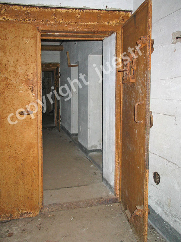
looking closer to the walls I believe that door frame and door were never installed
juestr 2010
room 14:
see room 21
room 15:
ventilation room with wooden door from room 13. From here at least the cartridge and shell stores were air-conditioned by preheated (or cooled?) air. The water-air heat exchanger and filters are still in place, idem traces of electrical equipment. Motor and fan(s) are left. Probably also a refrigerator. This place looks very much like a similar one in Austratt, seen on a picture with unfortunately few details. In addition, at the highest point of the ceiling, is the typical "expansion-vessel" (Ausdehnungsgefäß) for central heating boilers - but no trace of boiler / heater. (>> see room 20) nor an opening in the wall for a chimney. The communicating pipes between this vessel and the heater go down through the floor. From a french report we know that (at least) the shell stores had central heating. We see it also in the cartridge store. This means that a heater must exist and be situated near the expansion vessel and the radiators. The only logical location for me is the similar room just below in the basement (room 20).
Images here:
viewtopic.php?f=70&t=181003&hilit=warmw ... r#p1619730
Discussion also here:
viewtopic.php?f=70&t=181003&p=1994364&h ... r#p1744760
rooms 16 + 18:
A Gasschutztür similar to 19P7 leads into the right square cartridge store. Unfortunately, this is the last visitable room because the turret pit 17/23 was filled up with sand in 1997. Here no electro-mechanical transport systems (runways) were installed because of the relatively low weight of "Vor- and Hauptkartusche" (20 kg + 40 kg) which were transported manually to the transfer openings (hatches) in the wall. The two hatches with steel-plate locks for passing cartridges and powder bags to the powder-platform of the turret are at the same position like onboard. The locks were, for sure, the same system as in Austratt.
room 17 and 23:
These rooms are the "turret-pit" consisting of a lower rectangular part over the 2 floors of S473 and a cylindrical part above. If adjusted to the original naval turret these rooms must have had exactly predefined dimensions in x- and z-direction (width and height). By examining attentively "historical" pictures before filling up we see the curious situation that the diameter of the upper cylinder is bigger than the width of the rectangular room below, but nearly equal (slightly less) to the depth.
image (slide) from Dora taken by me 1981/82
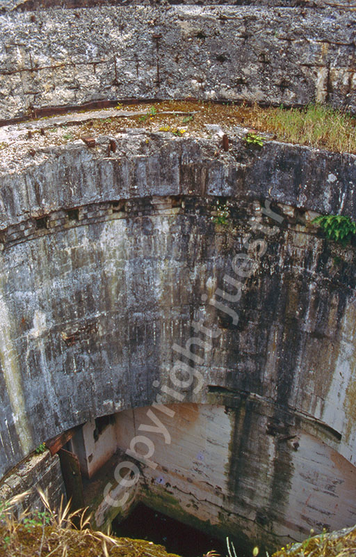
The measured depth of the rectangular distribution rooms is 532 cm, the diameter of the cylinder has been reported as 526 cm, the width MUST have 30-40 cm less. So it seems being evident that the width of these rooms is exactly the same as onboard = 490 cm. Onboard this cylindrical part is slightly conical. The position of the hatches going through the wall corresponds to the onboard width of the roller conveyors. Similar ones can be seen on pictures of Austratt.
room 19
Downstairs from room 15 we arrive at the "shell-level". with a hatch in the wall to the shell store (22) and a hole in the ceiling covered by a cap. The shell handling has been described in viewtopic.php?f=70&t=228085&hilit=shell+handling
and is in so far identical to Austratt. The doors to rooms 19 and 20 are both "Gasschutztüren".
room 20:
Heater room, situated just below ventilation room 15. Here arrive the pipes, going down from the “Ausdehnungsgefäß” in room 15 to the missing scrapped heater (Warmwasserkessel).
room 21/14:
Coal bunker. This small room is an open pit from the ground floor (room 14) to the basement with a small opening of ca. 40x60cm at the bottom (room 20) in the wall towards the heater room. This opening is still under water.
For a long time this pit was a mystery for Jazote and me. Before knowing about the shell handling I thought more about a not yet finished kind of elevator shaft for the ammunition handling but I doubted it because of the size and position of the wall openings.
Discussion and images here:
viewtopic.php?f=70&t=228085&hilit=shell ... g#p2098903
So with my latest regards and today’s knowledge it is more then probable a coal bunker.
room 22:
Shell store, communicating with room 19 by a large hatch for shell handling and a door "Gasschutztür". In this room because of the weight of the shells (ca. 125 kg) runways (monorails) at the ceiling are necessary The situation is the same as in the S473 of the “Batterie Seydlitz” (Ile de Groix). Looking to a picture in the book “A la découverte des Fortifications de l´Ile de Groix” de A.Chazette (page 55) we see the slot/cavity in the ceiling for the central distribution runway with its switches. The system used for the 121 kg shells looks very much like what can be seen on the plans of the cartridge store at "Lindemann" and at Hanstholm (S468 basement).
Lindemann cartridge circuit with switches
Who may contribute to details (drawings other than those in the American report or images) of the central runway with switches? High resolution images from the runway-switches (crossing) at Hanstholm or similar are welcome.
room 23:
see room 17
room 24:
shell store like room 22. The room is filled up with shells by using the two original onboard roller conveyors going through the turret pit (room 23)
Many thanks to Cathérine, a french “english teacher”, and Jean-Luc who had a look to my text.