S473 / S483 combined for 2 x 20,3cm naval gun turret, Batt. Karola (Ars)
Re: S473 / S483 combined for 2 x 20,3cm naval gun turret, Batt. Karola (Ars)
Air conditioning not only include heat or cold but also humidity.
Thanks,
Wim
www.petromax.nl
3D : http://www.petromax.nl/Hanstholm.html
http://www.petromax.nl/DeBeer.html
Wim
www.petromax.nl
3D : http://www.petromax.nl/Hanstholm.html
http://www.petromax.nl/DeBeer.html
Re: S473 / S483 combined for 2 x 20,3cm naval gun turret, Batt. Karola (Ars)
Hello JEF, hello Jos,jopaerya wrote: ↑08 Sep 2018, 08:46Hello Jürgen
It looks like that ammo rooms had also a radiator for warming, just like the bathroom .
You can see in the ammo room a large niche for a radiator ??
Maybe the Lufthitzer could also be used for ventilation when they running cold water in the pipes ??
Regards Jos
Thank you for the “three J´s” discussion.
As I thought, in Norway (Austratt) refrigerating is not necessary.
I did not pay much attention to the (small) radiator in the ammo-magazines even though this fact has been extra mentioned in the french after war report.
Whenever I have been inside the Bunker it was always cool (april, may, june, september) – and rare are the days when the temperature outside is near the freezing point. As the whole Bunker is covered by sand and 3,50 m concrete the temperatures will not change very much.
Within the limits of 15 degrees it is not so difficult to heat or to cool the magazines.
So the idea to use the heat exchanger as cooling device as well is really not bad. The groundwater is really “icy”.
Next time I will mesure both temperatures: inside air and water.
Conclusion (for the moment): no refrigerant compressor necessary for cooling, the radiator plus preheated air will be sufficient for warming
Re: S473 / S483 combined for 2 x 20,3cm naval gun turret, Batt. Karola (Ars)
Wim,
I did not see your post before.
As to the influence of humidity of the propellant and its storage I looked into the book “Leitfaden für den Artillerieunterricht in der Kriegsmarine, Teil I: Ballistik, page 21 (1938)”.
Here is written: ............ “Bei vorschriftsmäßiger (constant temperature) Munitionslagerung ist die Änderung des Feuchtigkeitsgehaltes des Pulvers sehr gering. Der Einfluß auf die Vo wird deshalb in der Front vernachlässigt.“
JEF knows certainly much more details about.
A major effect of the ventilation of preheated air is the exchange of warm air with higher water content against fresh air (during the night) with less water content, if necessary, thus decreasing a possible increase of humidity inside the building. Like at home !
Re: S473 / S483 combined for 2 x 20,3cm naval gun turret, Batt. Karola (Ars)
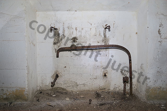
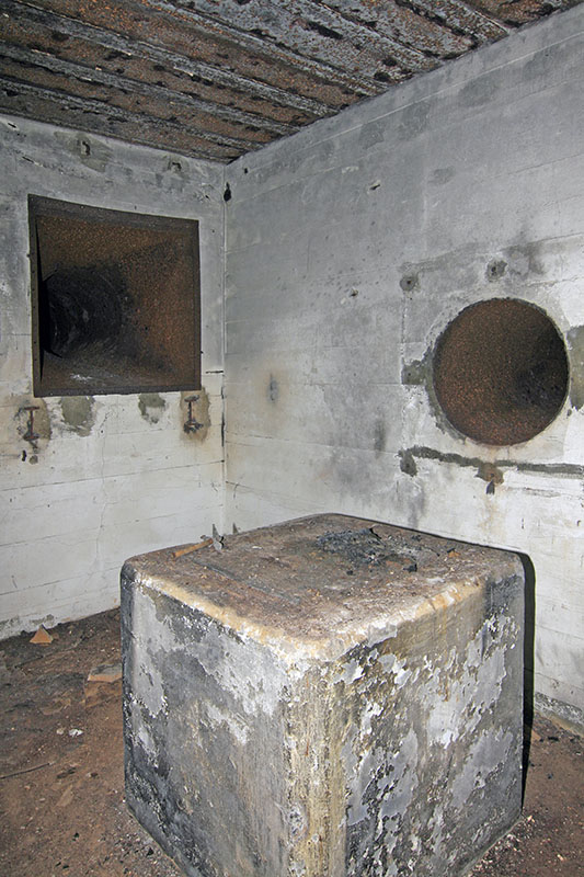
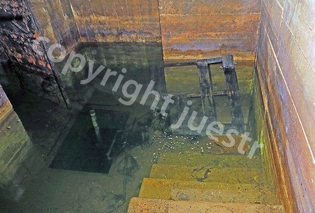
A picture from J.L.M. ( Jazote ) from the lower room behind the stairway . 
- Attachments
-
Re: S473 / S483 combined for 2 x 20,3cm naval gun turret, Batt. Karola (Ars)
I can remember reading on this site, some months ago, that I would not have the guts to wet myself in order to measure the basements in Karola.
I am not going to name this guy, not out of respect, but since he is insignificant to me. He was, as very usual, wrong !
JLM
Re: S473 / S483 combined for 2 x 20,3cm naval gun turret, Batt. Karola (Ars)
Nice picture !
So the hallway with stairs is on the left ? With the amo door way / hatch.
Any change that there is also a picture of the other side of the room ? and the room left of the stairs going down ?
So the hallway with stairs is on the left ? With the amo door way / hatch.
Any change that there is also a picture of the other side of the room ? and the room left of the stairs going down ?
Thanks,
Wim
www.petromax.nl
3D : http://www.petromax.nl/Hanstholm.html
http://www.petromax.nl/DeBeer.html
Wim
www.petromax.nl
3D : http://www.petromax.nl/Hanstholm.html
http://www.petromax.nl/DeBeer.html
Re: S473 / S483 combined for 2 x 20,3cm naval gun turret, Batt. Karola (Ars)
Hello J.L.
Could you share any photo's of the large opening in the wall for the large gun rounds ??
Regards Jos
Could you share any photo's of the large opening in the wall for the large gun rounds ??
Regards Jos
Re: S473 / S483 combined for 2 x 20,3cm naval gun turret, Batt. Karola (Ars)
Hello,
Any new information about this magnificent site ?
Any new information about this magnificent site ?
Thanks,
Wim
www.petromax.nl
3D : http://www.petromax.nl/Hanstholm.html
http://www.petromax.nl/DeBeer.html
Wim
www.petromax.nl
3D : http://www.petromax.nl/Hanstholm.html
http://www.petromax.nl/DeBeer.html
Re: S473 / S483 combined for 2 x 20,3cm naval gun turret, Batt. Karola (Ars)
PART 2
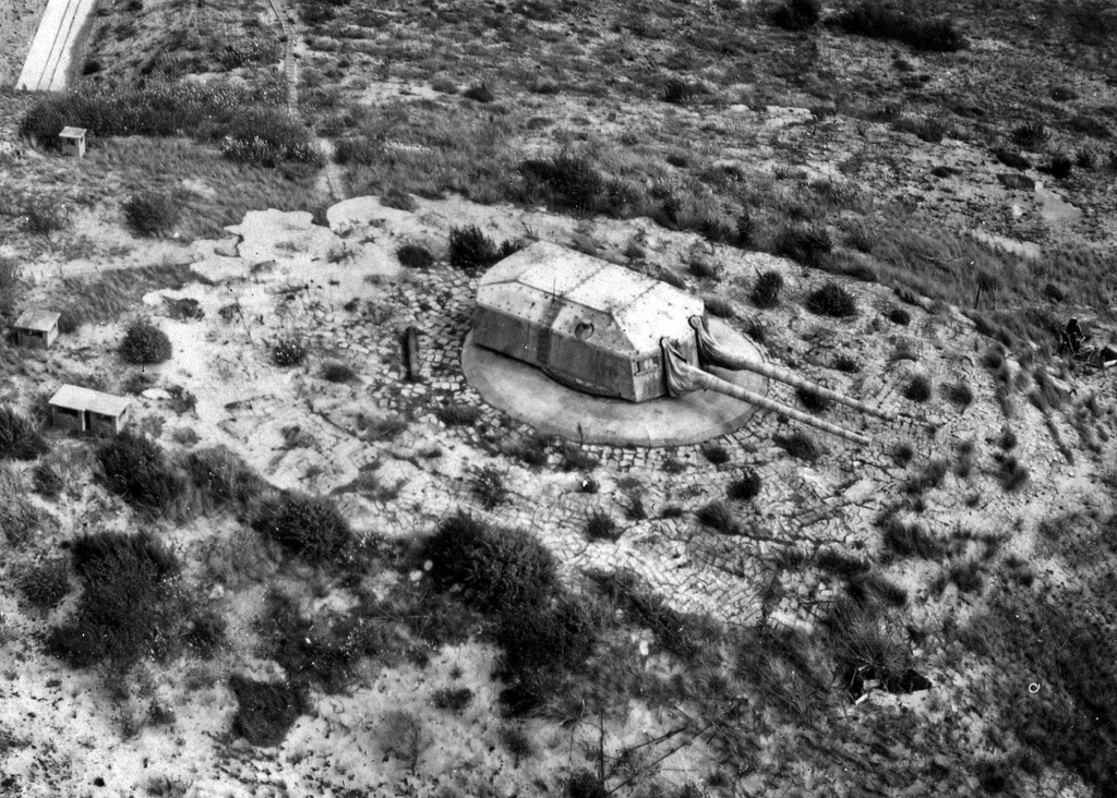
photo SHM 1945
Incredible, but another 2 years have gone - and we (my "3d-friend F.Lerch" and myself) are still working very intensively on my project to restore exactly this very interesting and unique Bunkersystem by a 3D model, as it was and as it is today.
Another 13 (!!) visits of Anton and Dora , up to 3 hours inside and mostly alone, some of them spent with friends of mine, made this reconstruction possible.
To know more about the "flooded" rooms in the basement of S473 I used (non-professional) "submarine equipment" for 3 explorations to take pictures and video clips.
Answering to Wim, the “latest” water level inside Anton was about 80 cm, 10 cm less than last year. Dora is completely filled with water up to the ceiling. As far as I know, since the scrapping it has never been empty.
In this report I refer to the first part at the very beginning of this thread. So all interested people please have a look to that first part before going on.
Summary:
- All assumptions made before, in 2018, have become true.
- The entrance door to room 16 (cartridge store) is a light armoured door, navy type T17 and not a “Gasschutztür”. For more details to this door type please have a look at A. Chazette’s book about these Kriegsmarine-doors.
- the outer shape of the bunker`s roof can be "seen" (slope) and determined at 2 different sides of the building. All the rest, covered by sand, might be equal and refers to the building of the Tirpitz battery.
- The thickness of the bottom plate is unknown, but seems to be 2,40 m (S473) or more.
- All predefined and all measured dimensions fit together. From the top of the outside concrete “collar” around the turret to the lowest bottom of the energy supply tunnel-pit, from the entrance walls and chimneys to the ammunition chambers - all fit without any cheating. This needed many attempts, many corrections and a lot of time.
And why? We sometimes ask ourselves For now, I can just give an answer similar to the answer made by the famous mountaineer Reinhold Messner: Because it (still) exists !
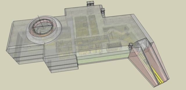
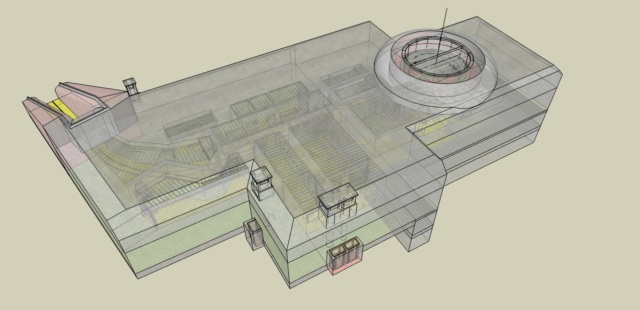
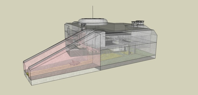
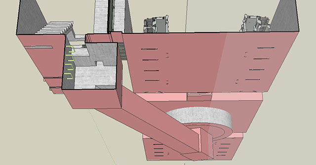
Some images of the model as an overview:
except the outer shape of the entrance walls (only Anton is visible and measurable) the whole model shows only "turret Dora".
overview
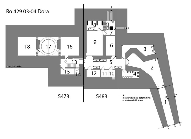
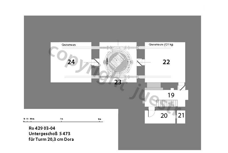
plan of rooms
Rooms 7 - 9 (machinery)
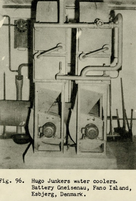
room 7 (water cooling)
The whole air circuit of this room could be explored and measured. The position of the pipes/tubes corresponds to the position of the "chimneys" outside on the roof. The 50 cm pipe on the left is just a communication from outside (chimney 1) to the inside of room 7. The pipe-hole in the wall was only covered by a grid or a "Düsenwandringlüfter". This combination of "wall-fan" and heat exchanger can be seen e.g. at Fanö and nearby in the tower S497.
The air circuit for the cooler device is very short and of a big diameter (65 cm), thus with low pressure loss. On the other hand a large amount of fresh air under the climate conditions of south-west France is needed to cool down the cooling water for the 2 Diesel-engines.
The heat exchanger (Rückkühler) is still an enigma for me. It cannot have been a standard "Einheitsrückkühler" as seen in Lindemann, Grosser Kurfüst, Fanö or even in the S497 ( Karola tower).
With the very big pipes and due to the fact that we only have the height of one floor as space for the exchanger, fan and pipes, the necessary height is missing.
This can easily be proved by comparing to the similar situation in a M219 Bunker where the diameter of the pipe is even less big (50 cm instead of 65) and the height of 2 floors is needed to install a standard "Einheitsrückkühler" with its pipes/tubes. So I think about a special but similar solution as Fanö arranged horizontally instead of vertically.
Problem: that solution must fit with all existing traces, bolts, 3d positions
room 8 (water tanks)
A major part of the piping for engine cooling is still present (from engines to tanks). For better remembering I made an additional video clip which follows the whole circuit.
Instead of three tanks I am thinking now about 2, certainly open above.
Unfortunately the second pipe going out of the heat exchanger is completely missing. So it is still not clear if the pipe returns to the water tanks or to an additional tank outside of the building as in other comparable cases (e.g. Kurfürst, Lindemann etc.). They are some reasons and traces to believe it. At least 2 pipes of the circuit are disappearing in the outer wall.
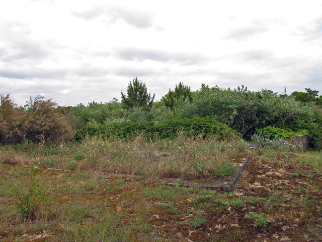
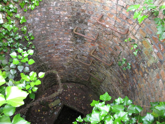
Outside between the 2 turrets, 80 m from Anton and 150 m from Dora, there is an open (double) concrete basin (Zisterne) with a rather big and deep well. I do not see any other reason for this installation at that place.
room 9 (engines)
An after war report tells about 2 engines, one of 100 HP (PS), the other one of 50 HP.
The "speed" is limited to 1000 rpm, only power units from 4 manufacturers could be used. The only real trace are the foundations with their bolts, the cooling pipes and the pipes for the generator cables.
As in some other batteries of high importance I suppose the same “small” Deutz engine (A4M517) were used. And it was a real pleasure to see, that using the exact (mm) dimensions as in Austratt, this engine fits exactly to the still existing bolts in the concrete.
Deutz A4M517R4, model 21,21 MB
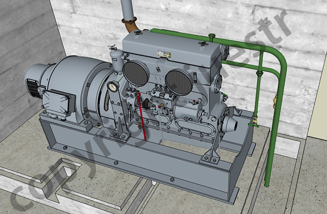
The cooling water pipe on the rigt side is different in Dora,simplified, the platform as well, like the model
It is much more difficult to find information and pictures about a 100 HP engine.
This will be the next challenge. Since some months I am looking to datas and informations.
Especially in Dora, parts of the switchboard were present and pictures were taken during the last 15 years. Additionally some historical photos are known. So the complete and standardized switchboard could be measured and restored in a very detailed manner.
image from 2005
Major parts of the engine exhaust pipes are still left as well.
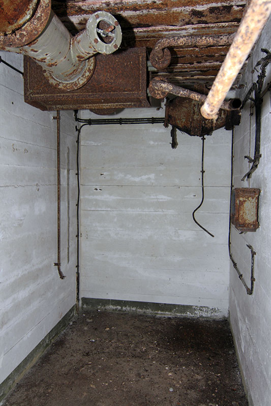
room 15 (air-conditioning)
From there at least the cartridge and shell stores were air-conditioned by preheated air. The water-air heat exchanger and filters are still in place. The WLE (Warmwasser-Lufterhitzer) is a special version because the dimensions differ from the known standardized types. In my mind a fan was needed for the air distribution into the ammunition stores. And a switchboard and its cables were still left on the walls.
Despite the little space I have realized the following arrangement (still under construction) by using standardized fan and pipes.
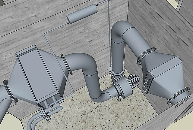
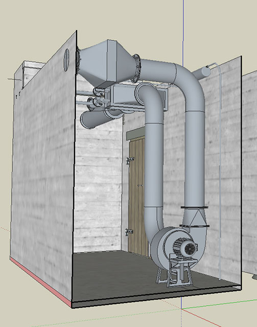
It doesn’t look bad, but I am unhappy because the electrical cable is situated on the lower right side of the wall. So during my latest visits I cleaned up the floor with a broom/brush and examined carefully the floor and the walls. Not a single trace of the installation for the fan is detectable!??
here a similar arrangement at St.Nazaire (?), picture from P.Fleuridas
room 19
What I stated or supposed 2 years ago, is sure now:
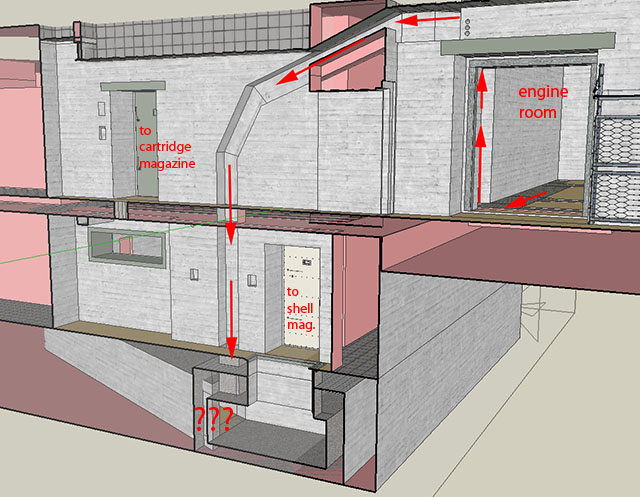
The energy supply for the turret passed by a visible and open cable conduit between the engine room 9 and room 19. And from here below the floor a supply tunnel of 80 cm height leeds to the center of the revolving turret (shell platform).
The following images shows a principal 3D pre-version of this situation. The bottom of the access pit leading to the supply tunnel is the lowest point of both buildings. The real situation is a little bit different.
This design corresponds principally to those of Austratt and Fjell.
this situation from june 2018 is/was extremely rare - normally the water is more or less troubled - and led me think about a pit and an supply tunnel starting from there, see part 1.
A picture extracted from one of my video clips shows a piece of cable still left in the transition area of this channel.
It was really a big chance to get this view because of nearly always troubled water ........
The shell transport from outside to the shell magazine has been treated in another thread :
viewtopic.php?f=70&t=228085&hilit=shell ... t#p2073599

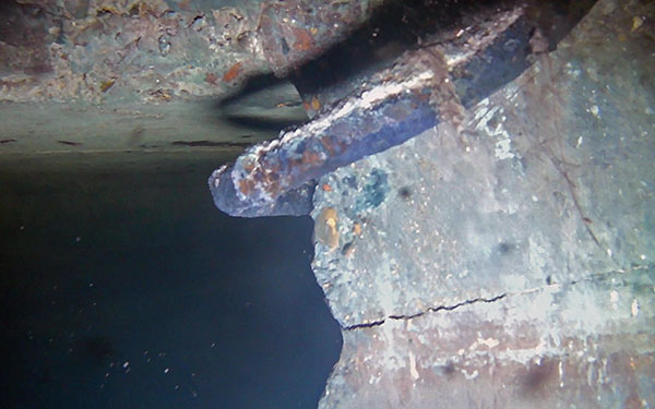
This means the transport is going from room 13 through an opening in the floor down to room 19. And from there by traversing a hatch in the wall directly into room 22 (and 24) where the shells are stored.
It is exactly the same installation and procedure as in Austratt.
here a view on the funnel-shaped opening and its vover from below (room 19)
room 20 (heater)
The chimney opening and the remaining pipes (over and under water) prove this room was the heater room. These pipes are leading from the boiler to the "Ausdehnungsgefäss" (expansion vessel) and the WLE one store above (room 15) and, very probably because of the still existing typical circuit, to the hot water "Druckwasser-Kessel" situated on the left side of the boiler . The size of the Ausdehnungsgefäß determines the heat-power (kcal) of the boiler.
heater pipes
opening to coal-bunker, room 21. Extract of video
room 22 + 24 (shell stores) . Hatch to room 19
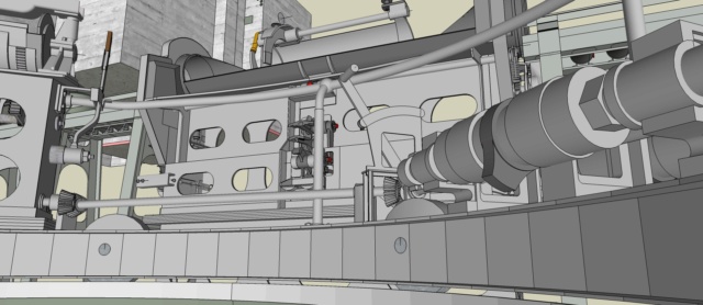
rooms 17 + 23 + 25 (turret pit)
The main reason for my interest to this battery is due to the fact that here a complete unmodified turret of a modern (pre war) German heavy cruiser (Seydlitz) had been installed. So more than 20 years ago I bought the reprint of the "Unterrichtstafeln für Geschützkunde, Band I, Seeziel from 1942", which deals all big naval turrets from 12,7 to 38 cm by detailed, but very small drawings.
Since last Christmas I have been focussing on the Bunker equipment, because the 3d-model of the buildings themselves are finished.
So for about six months I have worked mainly on the ammunition transport and charging equipment from the magazines to the turret, installed in the rooms 16, 17, 18, 22, 23, 24, 25. Not a single photo or image is available or even known (for me). That makes a 3d-reproduction very difficult - and, to be able to draw the model by using the above source, it is indispensable to understand the whole system, even the details.
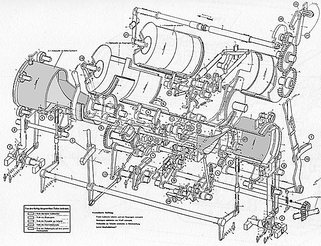
Not astonishing that I spent a lot of time in order to understand. I had some help because of a similar installation at Austratt but very different too. Different because of twin mount against triple mount, and different also because of the weight to be transported and of less space in a cruiser than a pocket-battleship.
parts of the installations in room 23
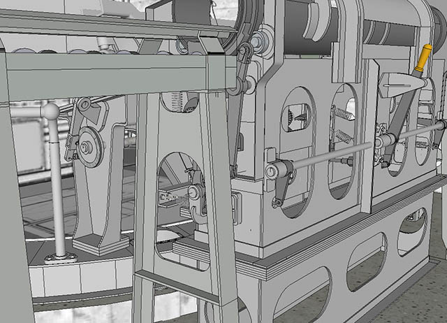
The construction of the static/fixed platforms around the turret are based on the traces and the measured remains of the beams in the concrete walls and on the design as built in Austratt.
The modeling of the turret itself with its rotating platforms has not yet begun.
As only overview-drawings as sectional-views exist, the model will be less detailed and accurate than the static surrounding equipment.
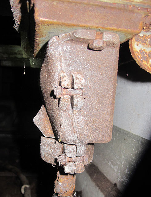
At least I show a comparison of a very unimpressive detail, one of several hundreds (thousands?),
cable plug from main-switchboard, room 9.
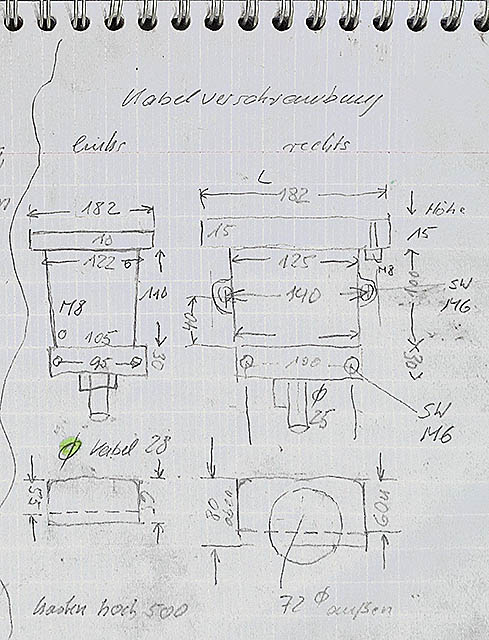
the belonging predefined (before visiting) sketch, filled with dimensions during the visit
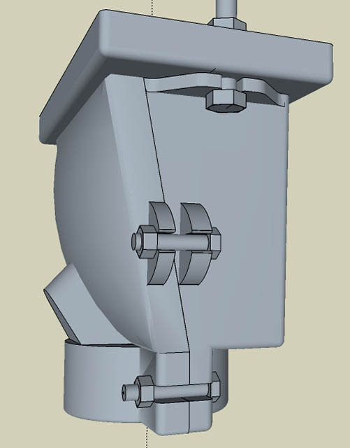
the result in the model.
Please note that the used 3d program sketchup 2016/17 is not really suitable to design cast parts with roundings in all three directions and different radii.
end of part 2
- whatever is told, there are no more other "secrets" to be found.
- I am very happy now about the results even if a lot of equipment and details are still missing.
- I am really afraid that this "challenge" will be a never ending story.
But so what !!!
.... and many thanks to Catherine and Jean-Luc for looking at my "german-english" and to all others who are concerned
merry Christmas, happy new year, - (if possible)
juestr (Jürgen Strecker)
photo SHM 1945
Incredible, but another 2 years have gone - and we (my "3d-friend F.Lerch" and myself) are still working very intensively on my project to restore exactly this very interesting and unique Bunkersystem by a 3D model, as it was and as it is today.
Another 13 (!!) visits of Anton and Dora , up to 3 hours inside and mostly alone, some of them spent with friends of mine, made this reconstruction possible.
To know more about the "flooded" rooms in the basement of S473 I used (non-professional) "submarine equipment" for 3 explorations to take pictures and video clips.
Answering to Wim, the “latest” water level inside Anton was about 80 cm, 10 cm less than last year. Dora is completely filled with water up to the ceiling. As far as I know, since the scrapping it has never been empty.
In this report I refer to the first part at the very beginning of this thread. So all interested people please have a look to that first part before going on.
Summary:
- All assumptions made before, in 2018, have become true.
- The entrance door to room 16 (cartridge store) is a light armoured door, navy type T17 and not a “Gasschutztür”. For more details to this door type please have a look at A. Chazette’s book about these Kriegsmarine-doors.
- the outer shape of the bunker`s roof can be "seen" (slope) and determined at 2 different sides of the building. All the rest, covered by sand, might be equal and refers to the building of the Tirpitz battery.
- The thickness of the bottom plate is unknown, but seems to be 2,40 m (S473) or more.
- All predefined and all measured dimensions fit together. From the top of the outside concrete “collar” around the turret to the lowest bottom of the energy supply tunnel-pit, from the entrance walls and chimneys to the ammunition chambers - all fit without any cheating. This needed many attempts, many corrections and a lot of time.
And why? We sometimes ask ourselves For now, I can just give an answer similar to the answer made by the famous mountaineer Reinhold Messner: Because it (still) exists !
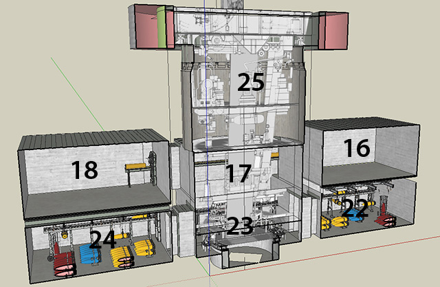
Some images of the model as an overview:
except the outer shape of the entrance walls (only Anton is visible and measurable) the whole model shows only "turret Dora".
overview
plan of rooms
Rooms 7 - 9 (machinery)
room 7 (water cooling)
The whole air circuit of this room could be explored and measured. The position of the pipes/tubes corresponds to the position of the "chimneys" outside on the roof. The 50 cm pipe on the left is just a communication from outside (chimney 1) to the inside of room 7. The pipe-hole in the wall was only covered by a grid or a "Düsenwandringlüfter". This combination of "wall-fan" and heat exchanger can be seen e.g. at Fanö and nearby in the tower S497.
The air circuit for the cooler device is very short and of a big diameter (65 cm), thus with low pressure loss. On the other hand a large amount of fresh air under the climate conditions of south-west France is needed to cool down the cooling water for the 2 Diesel-engines.
The heat exchanger (Rückkühler) is still an enigma for me. It cannot have been a standard "Einheitsrückkühler" as seen in Lindemann, Grosser Kurfüst, Fanö or even in the S497 ( Karola tower).
With the very big pipes and due to the fact that we only have the height of one floor as space for the exchanger, fan and pipes, the necessary height is missing.
This can easily be proved by comparing to the similar situation in a M219 Bunker where the diameter of the pipe is even less big (50 cm instead of 65) and the height of 2 floors is needed to install a standard "Einheitsrückkühler" with its pipes/tubes. So I think about a special but similar solution as Fanö arranged horizontally instead of vertically.
Problem: that solution must fit with all existing traces, bolts, 3d positions
room 8 (water tanks)
A major part of the piping for engine cooling is still present (from engines to tanks). For better remembering I made an additional video clip which follows the whole circuit.
Instead of three tanks I am thinking now about 2, certainly open above.
Unfortunately the second pipe going out of the heat exchanger is completely missing. So it is still not clear if the pipe returns to the water tanks or to an additional tank outside of the building as in other comparable cases (e.g. Kurfürst, Lindemann etc.). They are some reasons and traces to believe it. At least 2 pipes of the circuit are disappearing in the outer wall.
Outside between the 2 turrets, 80 m from Anton and 150 m from Dora, there is an open (double) concrete basin (Zisterne) with a rather big and deep well. I do not see any other reason for this installation at that place.
room 9 (engines)
An after war report tells about 2 engines, one of 100 HP (PS), the other one of 50 HP.
The "speed" is limited to 1000 rpm, only power units from 4 manufacturers could be used. The only real trace are the foundations with their bolts, the cooling pipes and the pipes for the generator cables.
As in some other batteries of high importance I suppose the same “small” Deutz engine (A4M517) were used. And it was a real pleasure to see, that using the exact (mm) dimensions as in Austratt, this engine fits exactly to the still existing bolts in the concrete.
Deutz A4M517R4, model 21,21 MB
The cooling water pipe on the rigt side is different in Dora,simplified, the platform as well, like the model
It is much more difficult to find information and pictures about a 100 HP engine.
This will be the next challenge. Since some months I am looking to datas and informations.
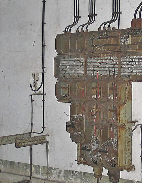
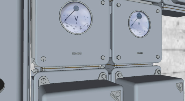
Especially in Dora, parts of the switchboard were present and pictures were taken during the last 15 years. Additionally some historical photos are known. So the complete and standardized switchboard could be measured and restored in a very detailed manner.
image from 2005
Major parts of the engine exhaust pipes are still left as well.
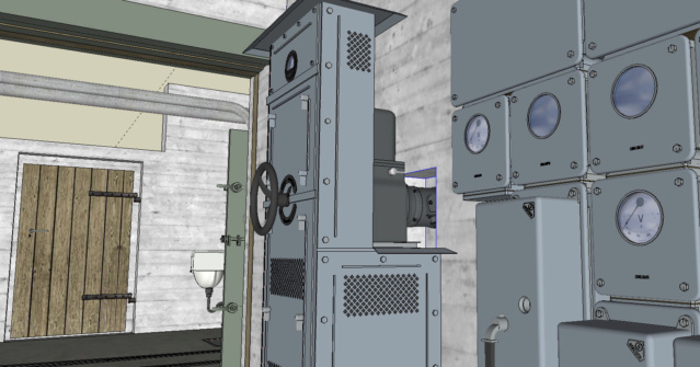
room 15 (air-conditioning)
From there at least the cartridge and shell stores were air-conditioned by preheated air. The water-air heat exchanger and filters are still in place. The WLE (Warmwasser-Lufterhitzer) is a special version because the dimensions differ from the known standardized types. In my mind a fan was needed for the air distribution into the ammunition stores. And a switchboard and its cables were still left on the walls.
Despite the little space I have realized the following arrangement (still under construction) by using standardized fan and pipes.
It doesn’t look bad, but I am unhappy because the electrical cable is situated on the lower right side of the wall. So during my latest visits I cleaned up the floor with a broom/brush and examined carefully the floor and the walls. Not a single trace of the installation for the fan is detectable!??
here a similar arrangement at St.Nazaire (?), picture from P.Fleuridas
room 19
What I stated or supposed 2 years ago, is sure now:
The energy supply for the turret passed by a visible and open cable conduit between the engine room 9 and room 19. And from here below the floor a supply tunnel of 80 cm height leeds to the center of the revolving turret (shell platform).
The following images shows a principal 3D pre-version of this situation. The bottom of the access pit leading to the supply tunnel is the lowest point of both buildings. The real situation is a little bit different.
This design corresponds principally to those of Austratt and Fjell.
this situation from june 2018 is/was extremely rare - normally the water is more or less troubled - and led me think about a pit and an supply tunnel starting from there, see part 1.
A picture extracted from one of my video clips shows a piece of cable still left in the transition area of this channel.
It was really a big chance to get this view because of nearly always troubled water ........
The shell transport from outside to the shell magazine has been treated in another thread :
viewtopic.php?f=70&t=228085&hilit=shell ... t#p2073599
This means the transport is going from room 13 through an opening in the floor down to room 19. And from there by traversing a hatch in the wall directly into room 22 (and 24) where the shells are stored.
It is exactly the same installation and procedure as in Austratt.
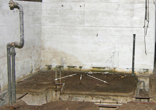
here a view on the funnel-shaped opening and its vover from below (room 19)
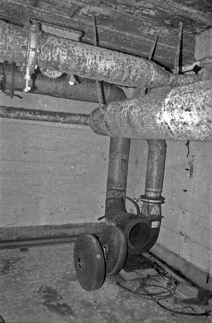
room 20 (heater)
The chimney opening and the remaining pipes (over and under water) prove this room was the heater room. These pipes are leading from the boiler to the "Ausdehnungsgefäss" (expansion vessel) and the WLE one store above (room 15) and, very probably because of the still existing typical circuit, to the hot water "Druckwasser-Kessel" situated on the left side of the boiler . The size of the Ausdehnungsgefäß determines the heat-power (kcal) of the boiler.
heater pipes
opening to coal-bunker, room 21. Extract of video
room 22 + 24 (shell stores) . Hatch to room 19
rooms 17 + 23 + 25 (turret pit)
The main reason for my interest to this battery is due to the fact that here a complete unmodified turret of a modern (pre war) German heavy cruiser (Seydlitz) had been installed. So more than 20 years ago I bought the reprint of the "Unterrichtstafeln für Geschützkunde, Band I, Seeziel from 1942", which deals all big naval turrets from 12,7 to 38 cm by detailed, but very small drawings.
Since last Christmas I have been focussing on the Bunker equipment, because the 3d-model of the buildings themselves are finished.
So for about six months I have worked mainly on the ammunition transport and charging equipment from the magazines to the turret, installed in the rooms 16, 17, 18, 22, 23, 24, 25. Not a single photo or image is available or even known (for me). That makes a 3d-reproduction very difficult - and, to be able to draw the model by using the above source, it is indispensable to understand the whole system, even the details.
Not astonishing that I spent a lot of time in order to understand. I had some help because of a similar installation at Austratt but very different too. Different because of twin mount against triple mount, and different also because of the weight to be transported and of less space in a cruiser than a pocket-battleship.
parts of the installations in room 23
The construction of the static/fixed platforms around the turret are based on the traces and the measured remains of the beams in the concrete walls and on the design as built in Austratt.
The modeling of the turret itself with its rotating platforms has not yet begun.
As only overview-drawings as sectional-views exist, the model will be less detailed and accurate than the static surrounding equipment.
At least I show a comparison of a very unimpressive detail, one of several hundreds (thousands?),
cable plug from main-switchboard, room 9.
the belonging predefined (before visiting) sketch, filled with dimensions during the visit
the result in the model.
Please note that the used 3d program sketchup 2016/17 is not really suitable to design cast parts with roundings in all three directions and different radii.
end of part 2
- whatever is told, there are no more other "secrets" to be found.
- I am very happy now about the results even if a lot of equipment and details are still missing.
- I am really afraid that this "challenge" will be a never ending story.
But so what !!!
.... and many thanks to Catherine and Jean-Luc for looking at my "german-english" and to all others who are concerned
merry Christmas, happy new year, - (if possible)
juestr (Jürgen Strecker)
Last edited by juestr on 08 Dec 2020, 12:20, edited 3 times in total.

Re: S473 / S483 combined for 2 x 20,3cm naval gun turret, Batt. Karola (Ars)
Only a blind-bunker freak could not consider this fabulous work.
Thanks Jürgen for our Sankt-Nikolahaus gift.
Thanks Jürgen for our Sankt-Nikolahaus gift.
Re: S473 / S483 combined for 2 x 20,3cm naval gun turret, Batt. Karola (Ars)
Well done.
Great 3D model.
Are the video's also available for us to enjoy?
For round corners in SU consider the add on Round corner from fredo
Great 3D model.
Are the video's also available for us to enjoy?
For round corners in SU consider the add on Round corner from fredo
Thanks,
Wim
www.petromax.nl
3D : http://www.petromax.nl/Hanstholm.html
http://www.petromax.nl/DeBeer.html
Wim
www.petromax.nl
3D : http://www.petromax.nl/Hanstholm.html
http://www.petromax.nl/DeBeer.html